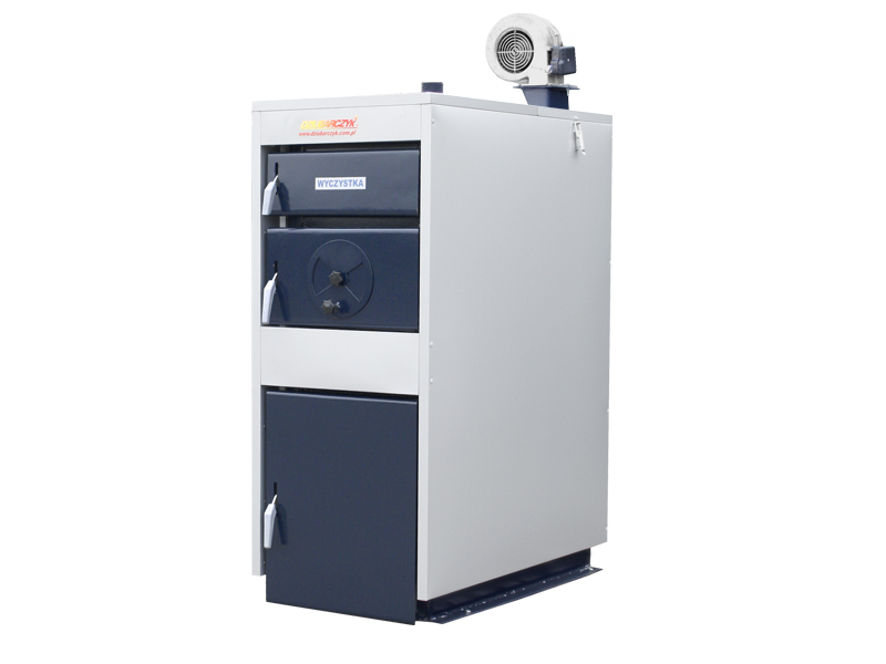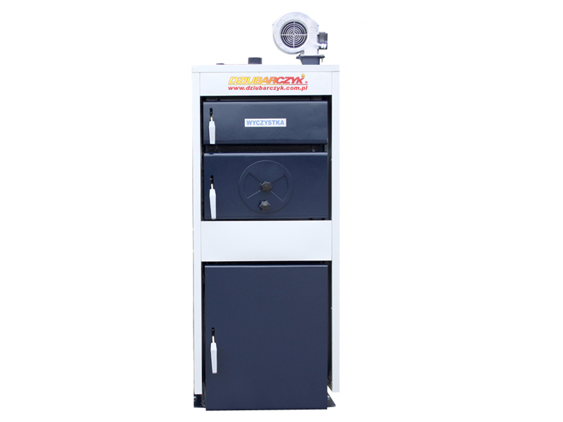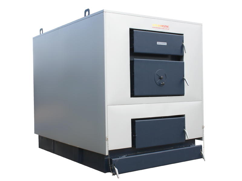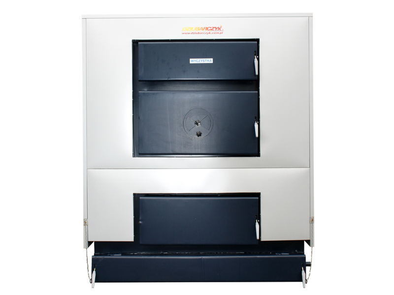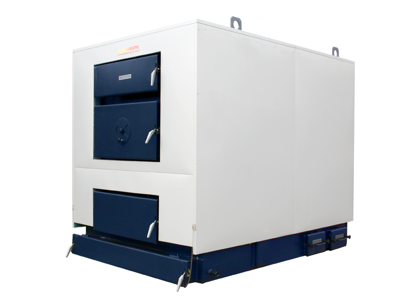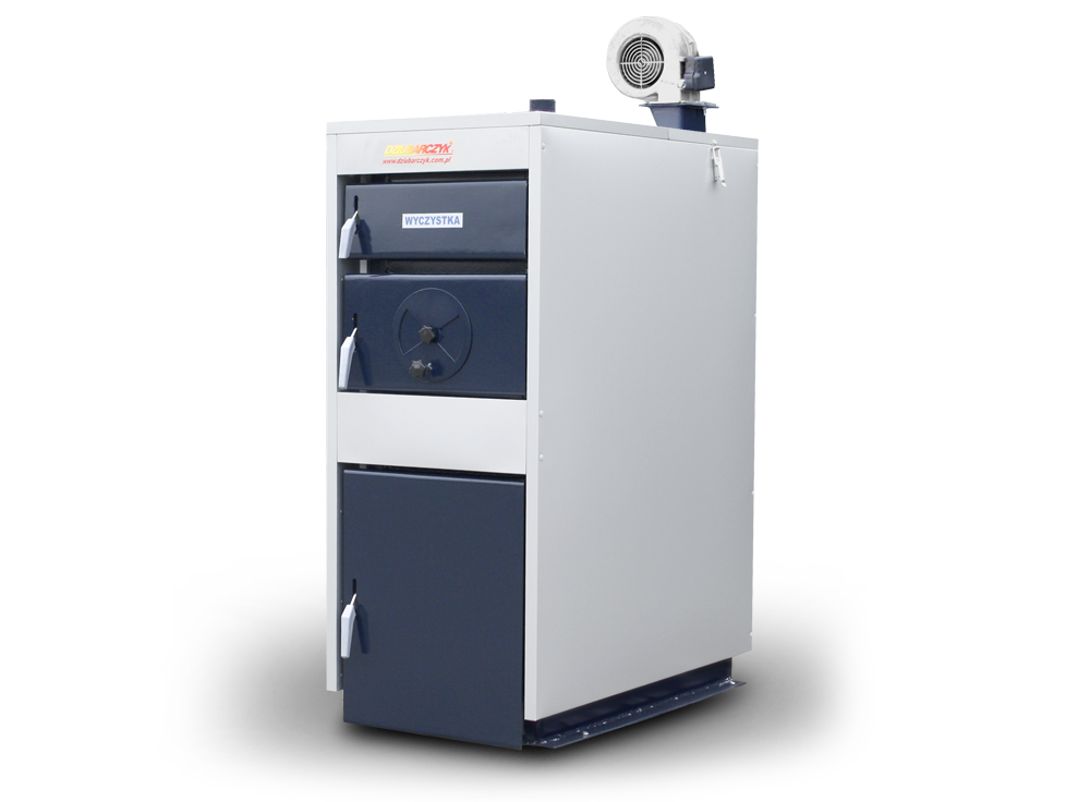
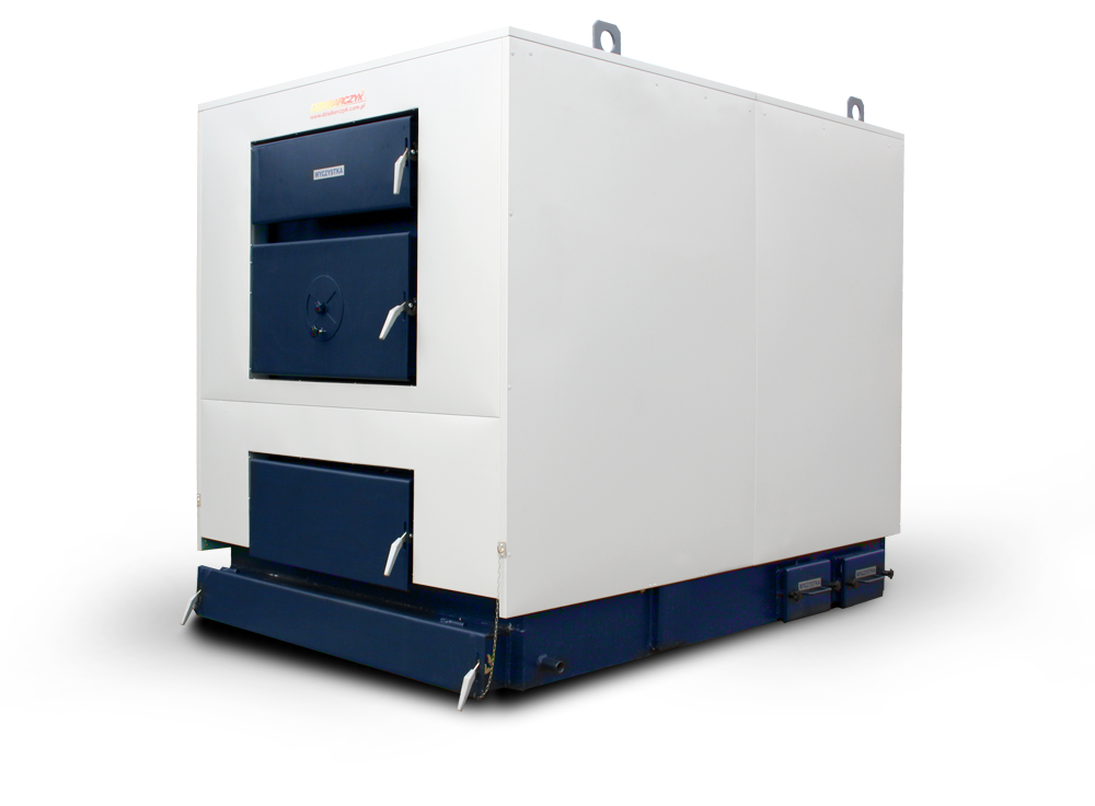
KWM-S
central heating furnaces for all kinds
of fuel with controller and blower
Central heating furnaces
KWM-S central heating furnaces are appliances with adjustable combustion process, designed mainly for water heating to the temperature not exceeding 90°C.
Advantages
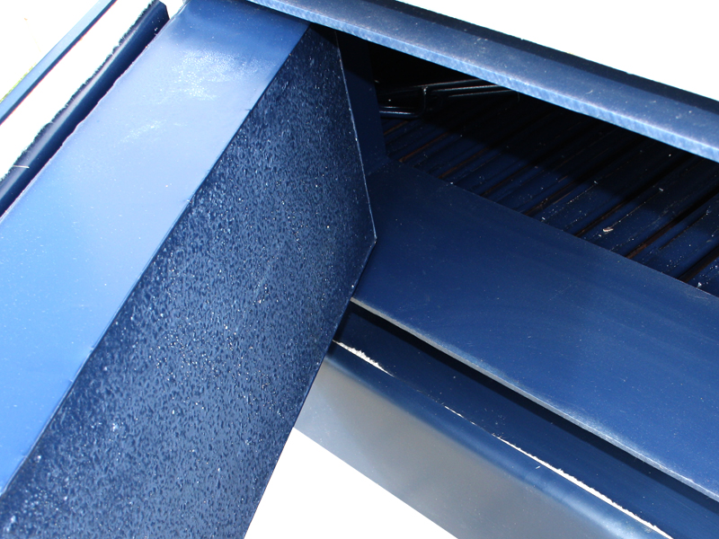
- STEEL OF THE HIGHEST QUALITY – boiler sheets P265GH
- EFFICIENCY – the efficiency of the boilers going up to class A
- VERY BIG FILLING CHAMBER
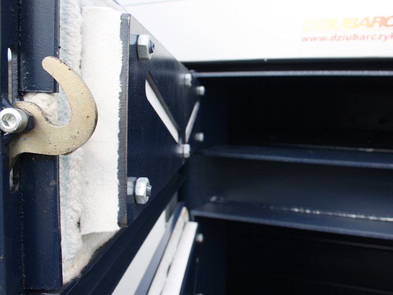
- BIG AND CONVENIENT DOOR – with an option to configure left / right
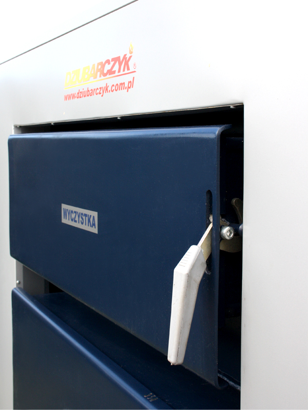
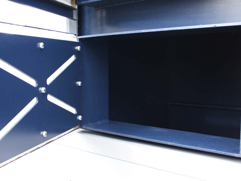
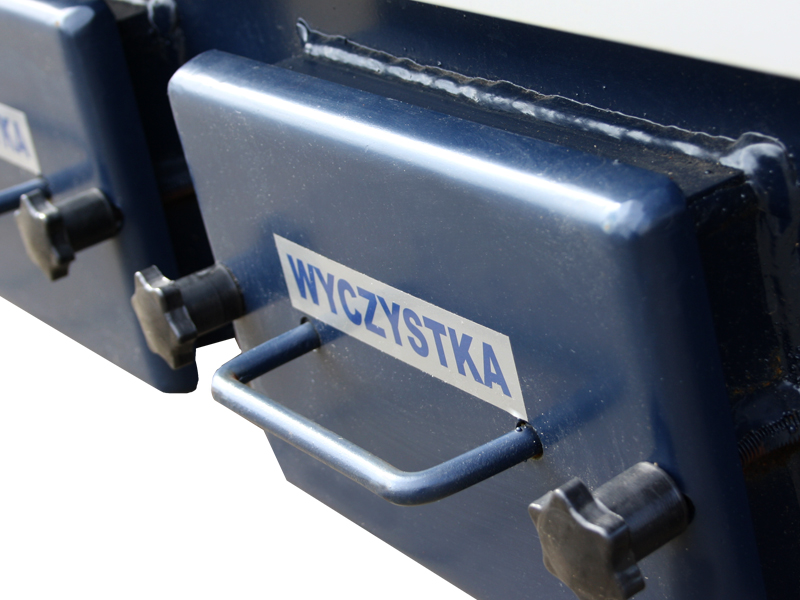
- CLEANOUT AT THE FRONT – a convenient way to clean the boiler
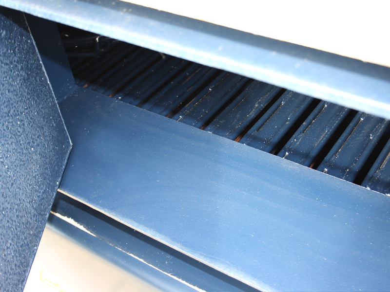
- SIMPLEST CLEANING OF THE BOILER – access to channels by opening the front door
Fuel type:
fine coal
coal
wood
briquette
These central heating furnaces are used in central heating installations in all types of residential buildings, trade halls, workshops, farms, hothouses, schools, etc.
They are produced with capacities of 19 - 500 kW. An additional advantage of those furnaces is very little harmfulness to the natural environment.
Central heating furnaces must be installed in open-system installations only. They can work in gravity or pump systems.
KWM-S - 500 kW

| Detailed list | Technical specifications of KWM-S | ||||||||||||||||
| Rated power | kW | 19 | 25 | 38 | 50 | 62 | 75 | 95 | 125 | 150 | 200 | 250 | 300 | 350 | 500 | ||
| Average power | kW | 9 | 12 | 19 | 25 | 31 | 37 | 50 | 62 | 75 | 100 | 125 | 150 | 175 | 250 | ||
| Boiler heating surface | m2 | 2 | 3 | 4 | 5 | 6 | 7,5 | 10,5 | 12,5 | 14 | 17 | 21 | 25 | 29 | 50 | ||
| Heating area | m2 | do 100 | 100 -150 |
150 -200 |
200 -250 |
250 -300 |
300 -380 |
380 -530 |
530 -630 |
630 -750 |
750 -1000 |
1000 -1300 |
1300 -1600 |
1600 -1900 |
2300 -3000 |
||
| Still burns | h | ~24 | |||||||||||||||
| Still burns at nominal power | h | ~8 | |||||||||||||||
| Filling up hopper capacity | kg | 35 | 45 | 60 | 75 | 95 | 120 | 165 | 195 | 285 | 360 | 430 | 565 | 725 | 885 | ||
| Thermal efficiency | achieved | % | 82 | 82 | 83 | 83 | 83 | 83 | 83 | 86 | 84 | 84 | 83 | 83 | 83 | 83 | |
| required | 75 | 75,5 | 76 | 77 | 77 | 77,5 | 78 | 78,5 | 79 | 79 | 79,5 | 80 | 80 | 80 | |||
| Maximum water temperature | ºC | 90 | |||||||||||||||
| Maximum working pressure | MPa | 0,15 | 0,25 | ||||||||||||||
| Test pressure | MPa | 0,25 | 0,35 | ||||||||||||||
| Required burnt gas draught | Pa | 23 - 30 | 45 - 50 | ||||||||||||||
| Required stack height | m | 5 | 5 | 5 | 6 | 6 | 7 | 7 | 8 | 9,5 | 11 | 12 | 13 | 13 | 15 | ||
| Chimney hole diameter | cm2 | 220 | 230 | 270 | 300 | 300 | 350 | 500 | 650 | 750 | 950 | 950 | 1300 | 1950 | 2400 | ||
| Boiler weight | kg | 327 | 410 | 490 | 580 | 665 | 800 | 1200 | 1400 | 1500 | 1750 | 2150 | 2760 | 3220 | 5300 | ||
| Capacity | dm2 | 112 | 125 | 170 | 215 | 255 | 315 | 450 | 530 | 560 | 590 | 650 | 780 | 930 | 1430 | ||
| Fuel | Hard coal - fine coal MI grade type 32.1 class 25/12 according to PN-82/G-97001-3 standard | ||||||||||||||||
| Basic dimensions | |||||||||||||||||
| Depth | exchanger | mm | 842 | 954 | 1014 | 1074 | 1124 | 1174 | 1382 | 1512 | 1662 | 1742 | 1792 | 1938 | 2078 | 2660 | |
| total [G] | 1097 | 1249 | 1344 | 1424 | 1494 | 1544 | 1792 | 1962 | 2227 | 2307 | 2357 | 2503 | 2693 | 3260 | |||
| Width | exchanger | mm | 422 | 514 | 564 | 634 | 694 | 784 | 858 | 872 | 924 | 1054 | 1164 | 1341 | 1526 | 1870 | |
| total [D] | 542 | 634 | 684 | 754 | 814 | 904 | 978 | 952 | 1004 | 1134 | 1244 | 1421 | 1606 | 2998 | |||
| Height | exchanger | mm | 1032 | 1097 | 1212 | 1217 | 1292 | 1392 | 1542 | 1466 | 1500 | 1550 | 1650 | 1750 | 1780 | 1900 | |
| total [H] | 1290 | 1355 | 1470 | 1475 | 1550 | 1650 | 1800 | 1851 | 1885 | 1935 | 2035 | 3135 | 3165 | 2200 | |||
| Diameter of supply and return connecting pipe ø | mm | 60x4 | 60x4 | 60x4 | 60x4 | 76x4 | 76x4 | 89x4,5 | 89x4,5 | 89x4,5 | 108x4 | 108x4 | 133x4 | 133x4 | 150x4 | ||
| Flue diameter | mm | 125 | 130 | 160 | 160 | 180 | 180 | 220 | 230 | 250 | 280 | 280 | 320 | 400 | 500 | ||
| Power consumption | W | 60 | 60 | 60 | 60 | 60 | 2x60 | 2x60 | 370 | 370 | 370 | 550 | 550 | 550 | 550 | ||
Control device PŁOMYK
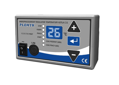
The Płomyk control device is designed for air blow control in fine coal boilers and for switching the circulating pump in central heating installations. The control device has blow-through function that is activated when the temperature exceeds the set value. The adjustable setting of central heating pump switching. The Płomyk control device meets domestic and industrial electromagnetic compatibility standard (CE sign). The control device is characterized by a very easy operation and reliable action.
Technical specification:- Temperature adjustment range 35 - 80°C
- Temperature measurement range 0 - 99°C
- Temperature that activates circulating pump is adjustable in the range of 10 - 70°C
- Blow-through control: 0 - 90 sec., break 1 -15 min
- Possibility of complete blow-through switching off P - 0
- Fluent blow adjustment
- Operation at surrounding temperature of 0 - 40°C
- Power supply ~230V/50Hz
- Acceptable outputs loading: - blow max 100W - circulating pump max 100W
- Adjustable power (revolutions) of the blower expressed in [%] from 30% to100%
- Range of automatic power switch of the blower before the demanded temperature is obtained: 2 to 10°C
- Relative air humidity 95%
- IP protection level 40
- Isolation class I
- Dimensions (width x height x depth) 125x75x50mm
- Electric protection 1,25 A
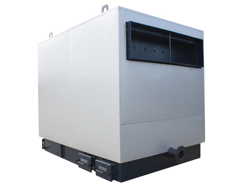
Boiler configurations
In the advanced boiler configuration we offer a few options:
- we offer a selection of the location of the feeder from the left-hand / right-hand side of the boiler
- we offer a selection of opening the door to the left / to the right
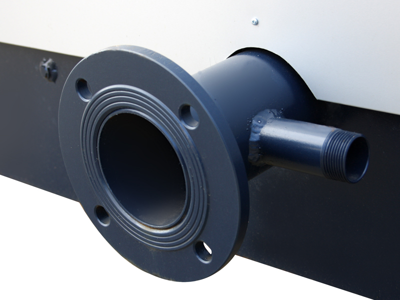
- we offer a selection of the diameter and kind of power and return connectors
- we offer a selection of the location of the power and return connectors
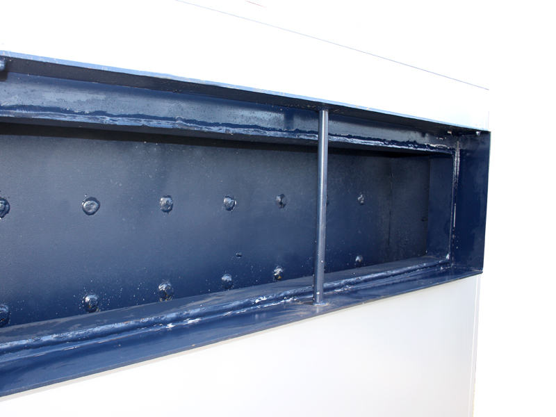
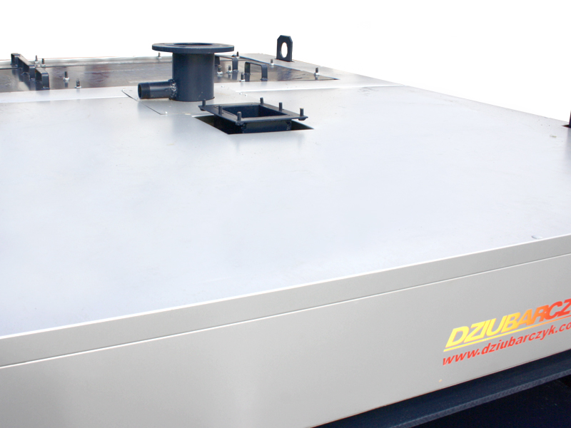
- we offer a selection of the shape and location of the boiler flue, e.g. elbow to the left, to the top etc.

1. The output of the flue
at the back in the middle.

2. The output of the flue
at the back (the elbow to the left).

3. The output of the flue
at the back (the elbow to the right).

4. The output
of the flue upwards.

5. The output of the flue
at the back (the elbow towards the back).

6. The output of the fluefrom
the top (the elbow to the left).

7. The output of the flue from
the top (the elbow to the right).
The shape of the flue
The shape of the flue can be selected in accordance with the customer’s expectations. We offer the circular shape / the square shape / the rectangular shape.